

Geo Examiner Underground Imaging Systems
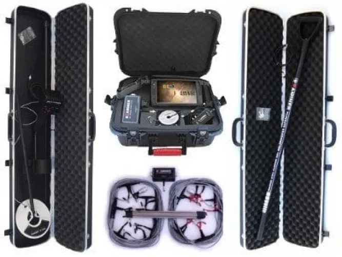
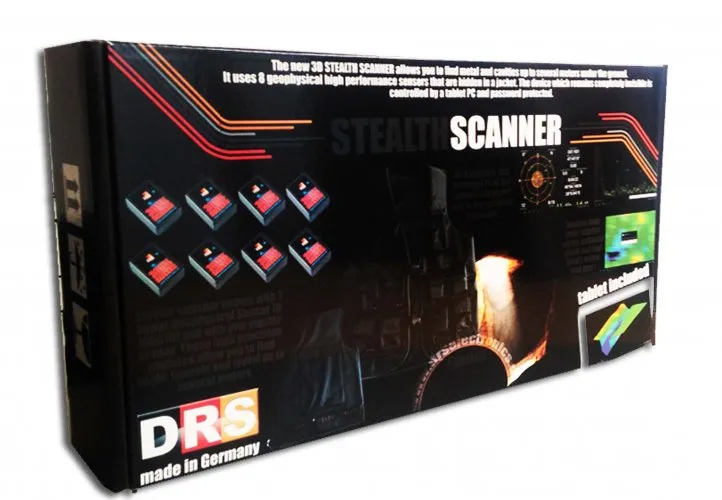
Geo Examiner underground imaging systems
The Geo Examiner category contains Full Set and Standard Package options. The central comparison is the measurement equipment behind those package names. “Full Set” alone does not identify every supplied sensor, and “Standard Package” should not be assumed to have an unchanging content list across all sales periods. Compare the written component lists with the method you actually intend to use.
The manufacturer associates the Geo Examiner platform with resistivity, magnetic measurement and metal-detector options. These methods measure different physical properties, and every component may not be included in every package. Identify the required method first, then the hardware needed to operate it. A three-dimensional presentation does not turn those different measurements into the same technology.
Geo Examiner Full Set versus Standard Package
When comparing Geo Examiner Full Set and Geo Examiner Standard Package, list the main unit, electrodes, cables, any additional sensors and viewing equipment separately. A component in a photograph should be checked against the delivery list. Its presence also does not automatically establish that the required application or licence is included. The supplied parts need to form a compatible working system.
A practical comparison describes the intended measurement from beginning to end. For a resistivity survey, which components are used between setting out electrodes and saving the result? If magnetic measurements are planned, is the relevant sensor included and what collection arrangement does it require? These questions establish whether a larger package provides useful additional capability. More equipment is not automatically better when it will remain unused.
Written component codes and quantities reduce confusion during later setup. Cable lengths and connector types also matter when planning the field layout. Offers using the same package name at different dates may have different contents. Keep the quotation date and package version with the price so that an earlier description is not mistaken for the scope of a current offer.
Ground contact in Geo Examiner resistivity surveys
Electrical resistivity measurements relate applied current to the resulting potential difference. Their interpretation depends on electrode arrangement and geometry. Electrode positions, spacing and contact conditions therefore belong with the record. A colour in the resulting display is not a conclusive label for a particular metal or cavity: moisture, material composition and geological conditions can affect the interpretation.
Assess surface access before planning the survey. Hard, rocky or covered surfaces may complicate electrode placement. Do not assume identical contact at every position. Follow the relevant instructions for connection and contact checks instead of improvising changes without understanding their effect. Documenting unusual surface conditions makes an unexpected value easier to investigate later.
When the measurement arrangement changes, record the new layout separately. Comparing the apparent size of coloured areas from surveys with different electrode spacing can be misleading. Preserve the origin and document the arrangement when repeating an area. A sketch with electrode numbers helps a team follow the connection order and reduces uncertainty when the data are reviewed away from the site.
| Method or component | Assessment focus | Interpretation limit |
|---|---|---|
| Resistivity | Electrode geometry and contact | Different ground conditions may produce similar values |
| Magnetic measurement | Sensor and nearby metal influences | A magnetic change is not a material name |
| Metal-detector option | Required hardware and operating mode | Its output differs from the other methods |
| 3D display | Data layout and processing settings | Visualisation does not create new measurements |
Reading Geo Examiner 3D imaging data
Identify the collection method before interpreting a three-dimensional view. Resistivity and magnetic datasets should not be read using assumed identical colour meanings. Learn the units, scale and automatic scaling behaviour of the program. Two files can look similar while using different value ranges; in that case, matching colours do not necessarily represent matching measurements.
Connect an interesting part of the image with its actual position on the field sketch. Missing information about the starting corner, line direction or point order can make this connection unreliable. Include the file name and scale information with screenshots used for review. Saving only a cropped coloured feature removes surrounding data that may be needed to understand the comparison.
If several methods will be compared, check the quality of each record first. Two indications in the same place are not automatically conclusive identification. Consider the physical properties to which the methods respond and any shared environmental influences. The datasets must also refer to the same spatial layout. State uncertainty in one record explicitly rather than allowing a convincing display from another method to conceal it.
Retain the original records before changing filters or presentation settings. Give processed copies meaningful names and note the reason for each change. This allows another reviewer to distinguish an observed measurement from a display choice. It also helps when a previously noticed feature appears to disappear after rescaling: the original information remains available for checking.
Geo Examiner prices and modular package selection
When reviewing Geo Examiner prices, mark which intended methods are supported by the supplied equipment. A user planning only resistivity measurements may have different requirements from a team combining several sensors. Consult the current Full Set and Standard Package product cards, then compare the difference with the sensor, software and accessory scope. Avoid assuming a fixed price or permanent package definition.
If adding equipment later matters, confirm compatibility before purchase. The same brand name does not establish that components from different versions connect directly. Ask about the complete expansion arrangement, including software, cables and adapters. This allows the initial cost and future plans to be assessed together rather than choosing only the lowest starting price.
Include setup time and staffing in the comparison. Positioning electrodes, arranging cables, numbering measurement locations and collecting the equipment afterwards all take time. A package with additional accessories does not solve a lack of access to the intended surface. During a demonstration, observe the process from opening the transport case to completing a record, not only the measurement itself.
Which Geo Examiner package best suits your survey?
The most appropriate package fully supports methods you can realistically apply. If the priority is consistent collection with one method, learning that setup and interpretation may be a manageable starting point. For a multi-method project, decide in advance how records will be separated, aligned to the same area and assigned for review. These decisions are more useful than selecting by the package name alone.
The main underground imaging systems category helps compare different equipment arrangements. For Geo Examiner, base the final choice on the delivery list, surface access and review process. Opening a sample file, explaining the measurement layout and identifying each supplied component makes the purchase scope concrete. Keep that information available for the first field session so that the demonstrated arrangement can be reproduced.
Frequently Asked Questions (FAQ)
Does Geo Examiner Full Set include every sensor?
Do not infer that from the name. The current written delivery list defines what is supplied.
Can the Standard Package be expanded later?
Confirm version, connection and software compatibility for the proposed additional parts.
Do resistivity colours directly identify metal types?
No. The measurements concern electrical properties, and different ground conditions can produce similar results.
Why does electrode contact matter?
It is part of the measurement arrangement. Check contact, connections and surface conditions according to the relevant instructions.
Does a three-dimensional image prove the system uses radar?
No. The display format and the physical measurement method are separate issues.